Posts

Showing posts from October, 2020

Impact test on aggregate (IS:5640-1970)

Image
  Objective - To determine the impact value of given road aggregate. Apparatus & materials required -  Impact testing machine. A cylindrical metal having internal diameter 75 mm and depth 50 mm. Tamping rod of 10 mm diameter and 230 mm long. IS sieve of sizes 12.5 mm, 10 mm and 2.36 mm. Balance Thermostatic oven Aggregate sample Theory - The aggregate impact value indicates a relative measure of the resistance of an aggregate to impact. The aggregate impact value is expressed as the percentages of fines formed in terms of the total weight of the sample.     Due to traffic loads, the road aggregates are subjected to impact and and there is possibility of aggregates breaking into smaller pieces. The road aggregate should be tough enough to resist fracture under impact. A test designed to evaluate the toughness of aggregate is called aggregate impact test.                                ...
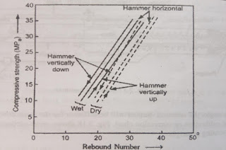
Rebound Hammer Test as per IS 13311(part-2)-1992.

Image
Rebound hammer test is a non-destructive concrete test which takes place to give the quality of concrete without damaging the concrete structure. It measures the elastic rebound of concrete and is used for determination of concrete strength. This test is conducted by Schmitt rebound hammer which carries a driving spring, a release button, casing, a plunger, a spring controlled hammer, tabular housing, mass and a scale. These units are arranged within a body such that when plunger hit the concrete surface, the mass rebounds from the plunger and the distance travelled by the mass gives the rebound number. This test can be conducted horizontally, vertically, upwards or downwards or at any intermediate angle. Procedure for rebound hammer test - Before starting the procedure, calibration of the hammer is required. The surface of concrete is cleaned . The hammer is held at right angle to concrete surface structure. After holding hammer in position, the plunger is made to hit the concrete sur...

Concrete Mix Design as per IS 10262:1982.

Image
 Concrete mix design deals with following steps. Step 1 - The target mean strength is calculated.         ft = fck + K x S where, ft = Target mean strength             fck = The strength of concrete mix which we want to design           K = 1.65            S = standard deviation Step 2 - The value of w/c ratio corresponding to target mean strength is taken from the graph. Step 3 - Maximum water content is taken from IS 10262:1982 corresponding to nominal size of coarse aggregate and slump 25 to 50 mm. Value of water content is increased by 3% for each additional 25 mm slump and reduced by 5-10% for plasticizer and 20% for superplasticizer. Requirement of water reduces with increase in normal size of aggregate. Step 4 - The quantity of cement is calculated.     wt. of cement = (wt. of water) / (w/c ratio) This value should not be less than minimum cement required cor...

Lug angle and tension splice - Introduction

Image
  Lug angle - Lug angle is an angle section of short length which connects the outstanding legs of angle section or member to the gusset plate.  It reduces the length of connection to the gusset plate and also reduces the shear lag effect.   When the lug angle is used, the unconnected length of main angle acts like a connected leg and hence entire cross-section area start resisting the tension. Thus, shear lag effect reduces and efficiency of the tension member increases.   Lug angle provides extra gauge line to accommodate the numbers of bolts.   Tension splice - Tension splice are the cover plates used on both sides of butt jointed members. A tension member is spliced when the length of section available is less than that of tension member required. when the members of different thickness are spliced, packing is required to fill the gap. The area of splices should be slightly more than that the member joined. It is also used when the size of the memb...

Multiple Choice Questions from Geometric Design of Highway.

Image
Go through these questions and test yourself. 1. The portion of the road surface which is used by the vehicular traffic is known as Carriage Way Shoulder Expressway All of these Answer - Carriage Way 2. Geometric design of highway deals with Cross section elements Sight distance consideration Horizontal alignment details All of the above Answer - All of the above 3. Which of the following term doesn't come under cross section elements ? Camber Kerbs Carriage Way Right of way Answer - Right of way 4. As per IRC recommendations, the coefficient of longitudinal friction varies from 0.35 - 0.38 0.30 - 0.35 0.35 - 0.4 0.4 - 0.45 Answer - 0.35 - 0.4 5. As per IRC, coefficient of lateral friction should be  0.12 0.15 0.18 0.20 Answer - 0.15 6. Longitudinal friction is useful in  Sight distance calculation Horizontal curve design Width of pavement calculation (a) and (b) both Answer - Sight distance calculation 7. An unevenness index value less than ________ is considered as good...